Effects of Electric Current Class 10 Solutions Maharashtra Board
Effects of electric current textbook solutions for class 10 :
- When a resistor is connected in an electrical circuit, heat is produced in it due to the current. This is known as the heating effect of current.
- Equipment such as water boiler, electric cooker, electric bulb make use of the heating effect of electric current.
- These days’ miniature circuit breakers (MCB) switches are used in homes. When the current in the circuit suddenly increases this switch opens and current stops. Different types of MCBs are in use. For the entire house, however the usual fuse wire is used.
- A magnetic field is produced around a straight current carrying conductor. If the current is unchanged, this magnetic field reduces as the distance from the wire increases.
- A device changing electrical energy into mechanical energy is known as electric motor.
Effects of electric current class 10 textbook solutions Pdf :
a. Fuse wire, bad conductor, rubber gloves, generator.
b. Voltmeter, Ammeter, galvanometer, thermometer.
c. Loud speaker, microphone, electric motor, magnet.
a. Fuse wire, bad conductor, rubber gloves, generator
Answer : The odd one out is generator. It is an electrical device for producing electricity. Fuse wire, bad conductor and rubber gloves have high resistance and are used for blocking electricity. Thus, they can be used as a safety measure against heavy electricity.
b. Voltmeter, Ammeter, galvanometer, thermometer
Answer : The odd one out is thermometer. It is an instrument for measuring the temperature of a body. Rest of the three are electrical instruments based on the phenomenon of electromagnetism and are used for measuring some electrical parameters such as current and voltage.
c. Loud speaker, microphone, electric motor, magnet
Answer : The odd one out is magnet. Loud speaker, microphone and electric motor are based on the phenomenon of electromagnetism.
Question 2: Explain the construction and working of the following. Draw a neat diagram and label it.
a. Electric motor
b. Electric Generator (AC)
a. Motor principle
Construction:
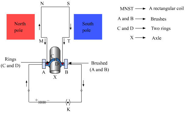
The given figure illustrates the internal parts of a simple electric motor. A motor consists of a rectangular coil MNST of insulated copper wire. The coil is placed between two magnetic poles such that the magnetic field acts normal on lengths MN and ST. The coil is connected with two carbon brushes at points A and B respectively. The inner sides of these carbon brushes are in contact with half rings C and D, which are insulated and in contact with an axle (not shown in the figure).
Working:
- When a current is allowed to flow through the coil MNST by closing the switch, the coil starts rotating anti-clockwise. This happens because a downward force acts on length MN and at the same time, an upward force acts on length ST. As a result, the coil rotates anti-clockwise.
- The current in length MN flows from M to N, and magnetic field acts from left to right normal to length MN.
- Hence, according to Fleming’s left hand rule, a downward force acts on length MN. Similarly, the current in length ST flows from S to T, and magnetic field acts from left to right normal to its length.
- Hence, an upward force acts on length ST. These two forces cause the coil MNST and the axle to rotate anti-clockwise.
- After half-rotation, the position of length MN and ST get interchanged.
- Simultaneously, half ring D comes in contact with brush A and half ring C comes in contact with brush B respectively. Hence, the direction of current in coil MNST gets reversed and flows through TSNM.
- An electric device that reverses the direction of current in a circuit is called a commutator. Thus, the split ring acts as a commutator of the electric motor.
- Now, due to the reverse direction of current in lengths MN and ST, an upward force acts on length MN, which pushes it up and a downward force acts on length ST, which pushes it down.
- As a result, the coil MNST further rotates anti-clockwise. The reversal of the current through the coil MNST repeats at each half-rotation, while its anti-clockwise rotation continues.
b. Electric Generator principle
Construction:
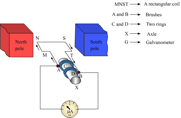
A generator consists of a rectangular coil MNST of insulated copper wire placed between two strong magnetic poles. The two ends of the coil MNST are connected with brushes A and B of rings C and D respectively. The inner sides of the rings are insulated. They are attached with an axle X, which can be rotated mechanically. Brushes A and B are connected with a galvanometer that can measure the flow of current in coil MNST.
Working:
- When the axle is rotated, lengths MN and ST move up and down respectively. Since lengths MN and ST are moving in a magnetic field, a current gets induced in these lengths caused by an electromagnetic induction.
- The direction of the induced current in both the lengths is given by Fleming’s right hand rule.
- Since length MN is moving upwards in the magnetic field that acts from left to right, the direction of the induced current will be from M to N.
- Similarly, the direction of the induced current in length ST will be from S to T.
- Hence, an induced current will set up in the coil in the direction MNST, which produces deflection in the galvanometer.
- After half-rotation, length MN starts moving down, whereas length ST starts moving up.
- The direction of the induced current in the coil gets reversed i.e., the induced current will now flow from T to M via S and N i.e., TSNM.
- Therefore, we can conclude that after each half-rotation, the direction of the induced current is reversed.
- This current is called an alternating current (AC). An AC reverses its direction after equal time intervals.
Question 3: Electromagnetic induction means-
a. Charging of an electric conductor.
b. Production of magnetic field due to a current flowing through a coil.
c. Generation of a current in a coil due to relative motion between the coil and the magnet.
d. Motion of the coil around the axle in an electric motor.
Answer : C. Electromagnetic induction means generation of a current in a coil due to relative motion between the coil and the magnet.
Question 4: Explain the difference:
AC generator and DC generator.
Answer :
| AC Generator | DC Generator |
|---|---|
| AC generator convert mechanical energy into AC electrical power | DC generator convert into mechanical energy into DC electrical power |
| It has sliprings | It has commutators |
| AC generator used power smaller motors and electrical appliances at homes | DC generator powers vary large electric motor |
| The initial cost of an AC generator is high | The initial cost of DC generator is low as compared to AC generator |
| In AC generator the electrical current reverse direction periodically | In DC generator the electrical current flow only one directions |
a. Electric motor
b. Galvanometer
c. Electric Generator (DC)
d. Voltmeter
Answer:
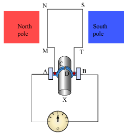
The device used for producing electricity is Electric generator (DC). It is based on the phenomenon of electromagnetic induction.
Working:
When the axle is rotated, lengths MN and ST move up and down, respectively. Since lengths MN and ST are moving in a magnetic field, a current gets induced in these lengths caused by an electromagnetic induction. The direction of the induced current in both the lengths is given by Fleming’s right hand rule.
In this arrangement, brush A always remains in contact with the length moving up, whereas brush B always remains in contact with the length moving down. Here, split rings C and D act as a commutator. In this case, the direction of the current induced in the coil will be from M to T via N and S for the first half-rotation, and from T to M via S and N for the second half-rotation of coil MNST. Hence, we get a unidirectional current called direct current (DC).
Answer : Short circuit occurs when naked live and neutral wires touch each other.
In such situations, the resistance of the circuit becomes very less. Now, according to Ohm’s law, current is inversely proportional to resistance. Thus, the decrease in value of resistance of the circuit raises the current to a significant amount. As a result, the wires become hot and sparks are caused by Joule’s heating effect of current.
Question 7: Give Scientific reasons.
a. Tungsten metal is used to make a solenoid type coil in an electric bulb.
Answer: Tungsten metal is used to make a solenoid type coil in an electric bulb because its melting point is very high. Thus, when a high amount of current is passed through it, it becomes red hot and emit lights without getting burnt.
b. In the electric equipment producing heat e.g. iron, electric heater, boiler, toaster etc, an alloy such as Nichrome is used, not pure metals.
Answer: In the electric equipment producing heat, such as iron, electric heater, boiler, toaster etc., an alloy such as Nichrome is used, not pure metals because of the following reasons:
(i) Resistivity of Nichrome is more compared to pure metal.
(ii) Melting point of Nichrome is high as compared to pure metal.
(iii) Nichrome does not get oxidised when heated in air whereas metal does
c. For electric power transmission, copper or aluminium wire is used.
Answer: For electric power transmission, Copper or Aluminium wire is used because they provide low resistance path to the flow of current. Thus, the power loss in the low resistance transmission wire will be less.
d. In practice the unit kWh is used for the measurement of electrical energy, rather than joule.
Answer: In practice, the unit kWh is used for the measurement of electrical energy, rather than joule. This is because joule is a very small unit and the energy consumption in day to day life is very large i.e. it comes in figures of 106 to 108. Thus, to reduce the complexity of handling such large figures, a bigger unit was required. This bigger unit used for the measurement of electrical energy is kWh and is related to joule as
1 kWh = 3.6 ×× 106 J
Hence, the energy reading commercially became simpler by using this bigger unit instead of joule.
Question 8:Which of the statement given below correctly describes the magnetic field near a long, straight current carrying conductor?
a. The magnetic lines of force are in a plane, perpendicular to the conductor in the form of straight lines.
b. The magnetic lines of force are parallel to the conductor on all the sides of conductor.
c. The magnetic lines of force are perpendicular to the conductor going radially outword.
d. The magnetic lines of force are in concentric circles with the wire as the center, in a plane perpendicular to the conductor.
Answer: The correct statement describing the magnetic field near a long, straight current carrying conductor is:
The magnetic lines of force are in concentric circles with the wire as the center, in a plane perpendicular to the conductor.
Question 9: What is a solenoid? Compare the magnetic field produced by a solenoid with the magnetic field of a bar magnet. Draw neat figures and name various components.
Answer:A solenoid is a long straight insulated wire, such as a copper coil, often wrapped around a cylinder-shaped body. The diameter of the solenoid is lesser than its length. It produces a magnetic field when electric current is passed through it.
Magnetic field produced by a solenoid is shown below:

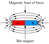
On comparing field lines produced by a solenoid with that produced by a bar magnet, we observe that they are very much identical. Thus, a solenoid acts as a bar magnet when current is passed through it.
Question 10:Name the following diagrams and explain the concept behind them.

Answer: a. It represents Fleming’s right hand rule used for finding the direction of induced current with respect to the directions of the magnetic field and motion of the conductor.
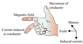
The direction of current induced in a conductor can be obtained by holding the thumb, the index finger, and the middle finger of your right hand mutually perpendicular to each other. In this situation, the thumb indicates the direction of the motion of the conductor, the index finger points along the magnetic field, and the middle finger points along the current induced in the conductor.
b. It represents Fleming’s left hand rule used for finding the direction of magnetic force when a current carrying conductor is placed in a magnetic field.
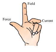
This rule states that if you stretch the thumb, index finger, and middle finger of your left hand such that they are mutually perpendicular to each other, then your index finger represents the direction of the field, the middle finger represents the direction of the current, and the thumb represents the direction of the force experienced by the conductor.
Question 11: Identify the figures and explain their use.

Answer: (a) Figure (a) represents a electric fuse. 1.electric fuse is a safety device that protects the wiring against excessive heating caused by an excess supply of current.
2.It melts when heavy current flows through the circuit, thereby causing the circuit to become open.

(b) Figure represents an MCB.
1.MCB is a device which functions as a fuse, but does not require replacement.
2. MCB falls down to break the circuit when heavy amount of current flows through it. Once the fault is rectified, the MCB is reset.

(c) Figure (c) represents a DC generator.
1. It is a device that generates electricity by rotating its rotor in a magnetic field. Thus, it converts mechanical energy into electrical energy.